
Overview#
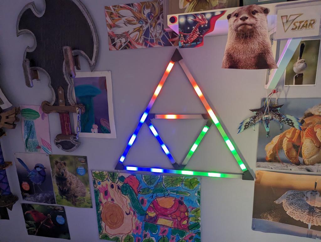
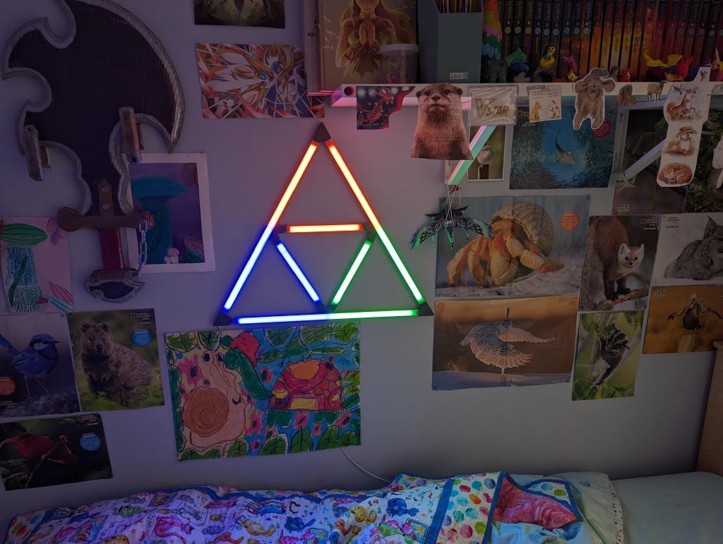
This is my second WLED project running on an ESP32 Microcontroller. It combines some aluminium profiles, with addressable RGB LEDs, custom 3d printed connectors where each segment can be removed as they are connected with usb-c and magnetic pogo connectors. This makes it easier to build, move and service (if any of the segments break). This tested my patience and ability to solder some very small contacts. You'll need a decent solder iron and a magnifying station to get this project done!
What you'll need#
- An ESP32 Microcontroller. I used a ESP32 D1 Mini
- WS2812b RBG Led strip - I used 144 LEDs/m
- INMP441 Microphone
- JST PH2.0mm 3-wire headers and leads (plenty of sellers on Aliexpress for these)
- 2x 10K resistor, 1x 330 resistor
- 1x 1000uF capacitor
- USB-C Male plugs
- USB-C Female connector
- 2.8mm Pogo pins
- 5 x 50cm Aluminium profiles w/ milky diffuser
- 1 x Makerverse 30 row protoboard
- A 3d printer (I have the Prusa Mini+)
How it was done#
3D printed connectors#
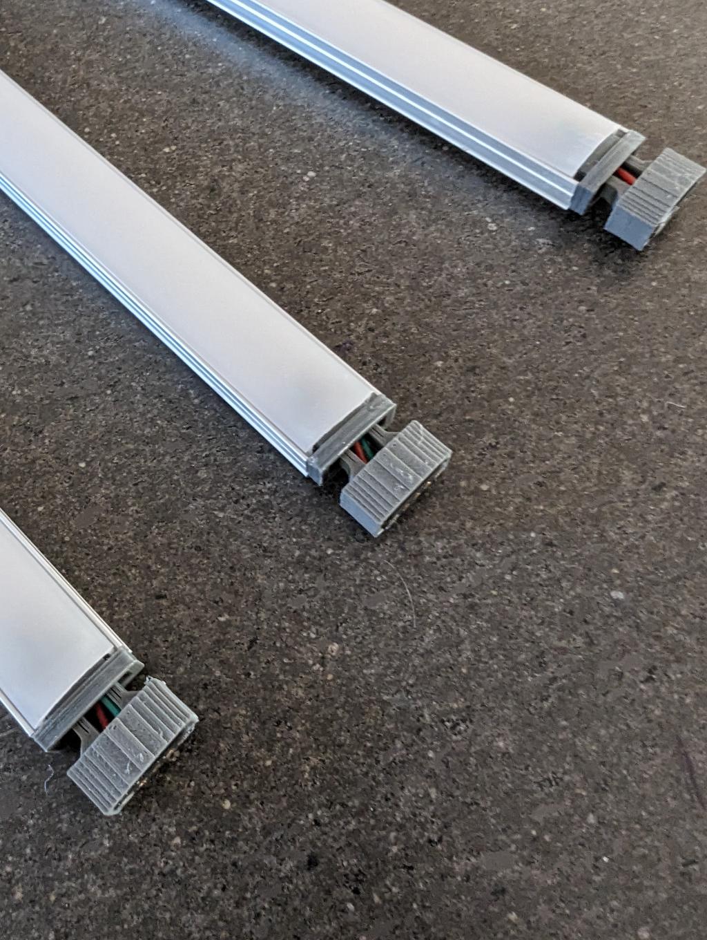
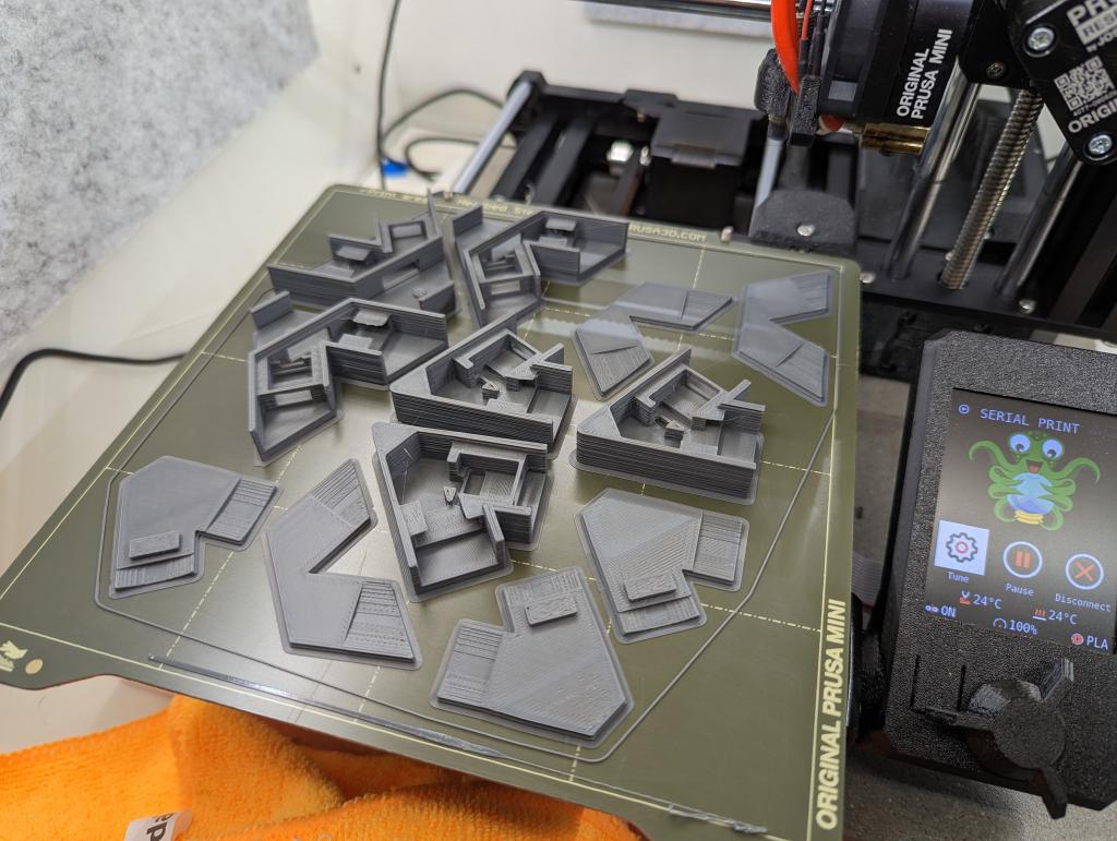 There are 3 corner connectors and 3 mid-way connectors. Each has a snap fit lid that fits on top to hide all the power connections.
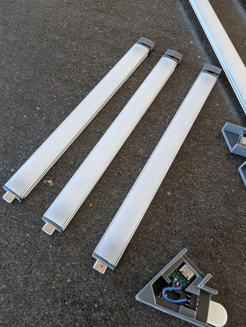
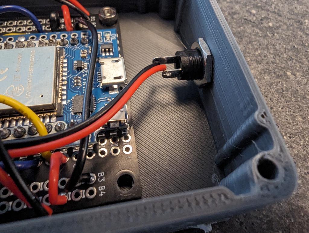
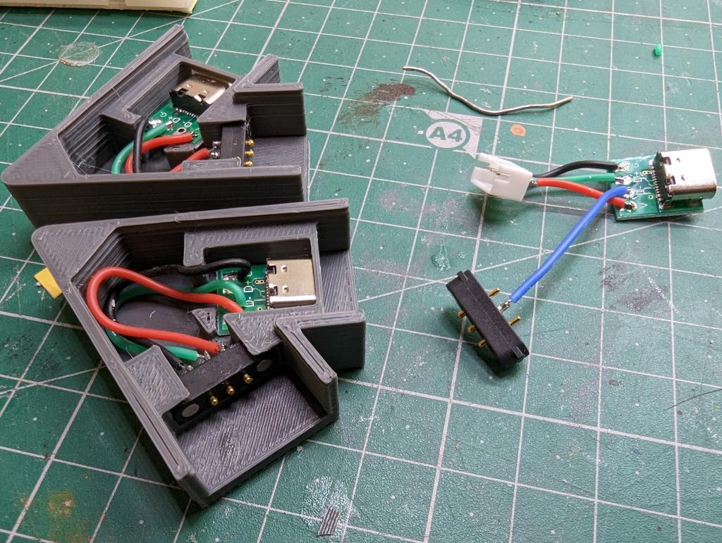 Each connector is a custom 3d printed design which fit a pogo pin / usb-c combination as shown above. They are connected straight thru, postive to postive, GND to GND and Data to Data. Be prepared to do LOTS of soldering. For each corner, you need to connect 3 wires from the pogo pins to the USB-C. The USB-C connector has an extra data pad which can be ignored except for the bottom left corner which is where power and data is brought in (using one of the JST connectors).
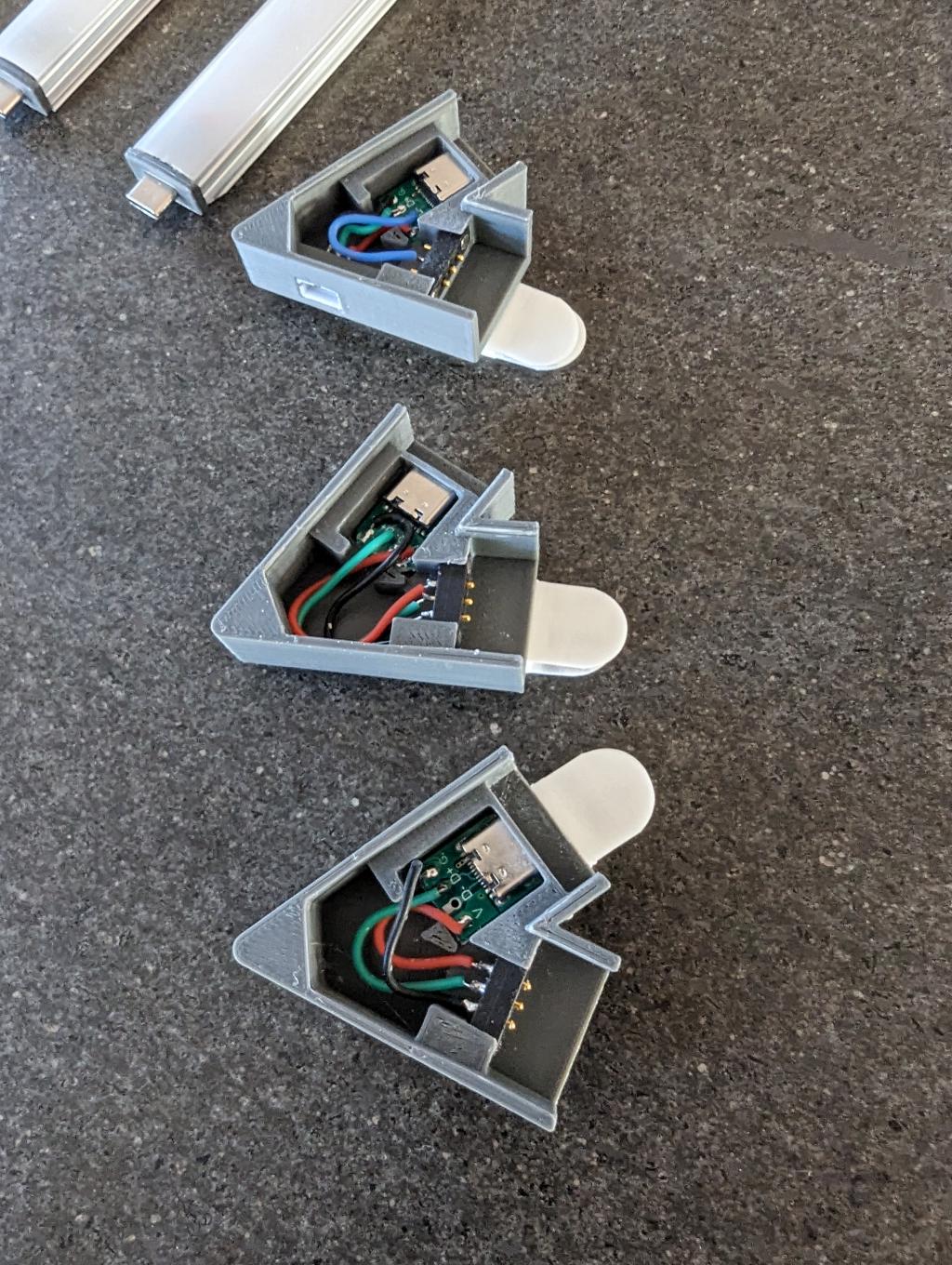
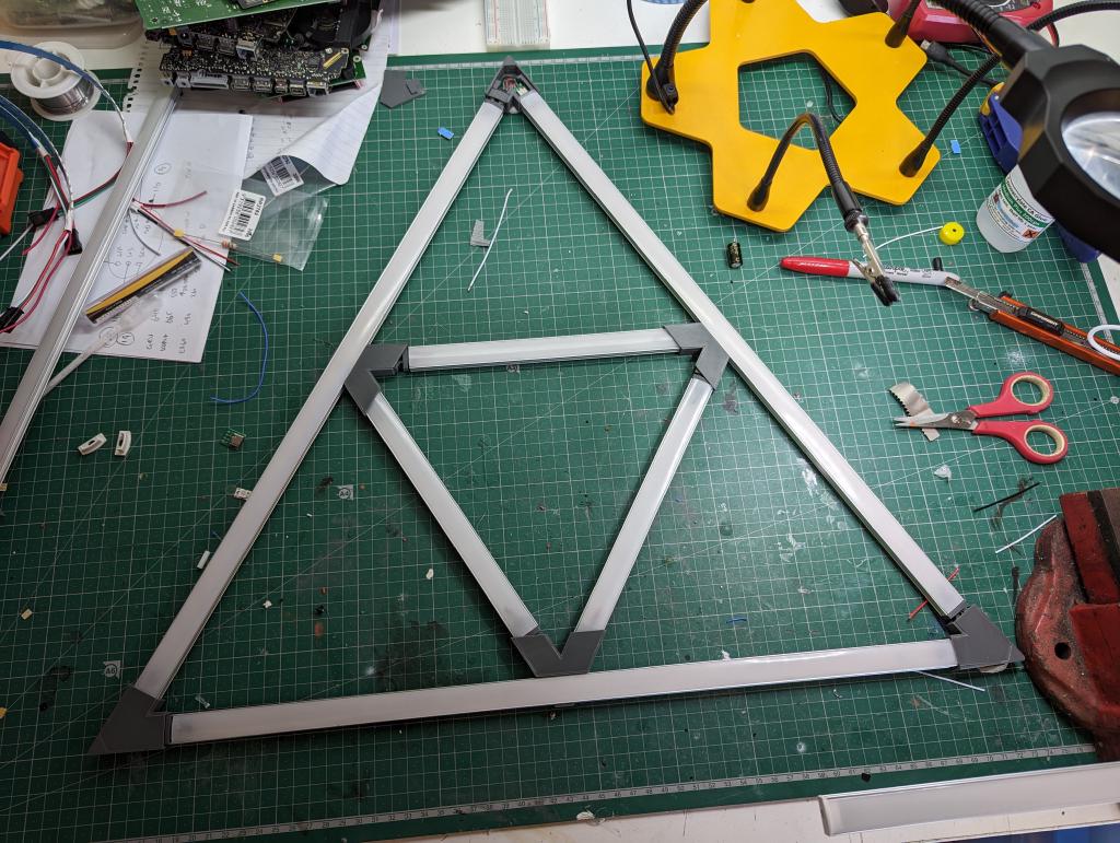
In this corner, loop the data line from the 3rd longer profile to the fourth usb-c pad (see the blue wire in the photos below). This allows you to run a wire along the inside of the profile, next to the LED strip, to reach the mid-point and connect to the inner triangle.
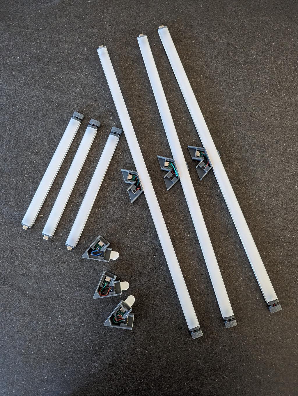
For each aluminium profile, print the 3d end caps which hold the opposite pogo pin on one end and USB-C male on the other. Again solder these connectors, this time to the LED strip. Once you're done, you should have 3x long sections (I used the full 50cm profile for these) and 3x shorter segments which are about half the size. Each profile will have a pogo pin connector on one end and a USB-C male on the other.
WLED Controller#
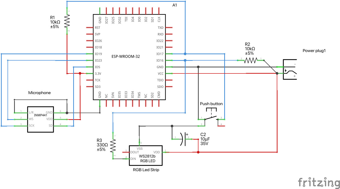
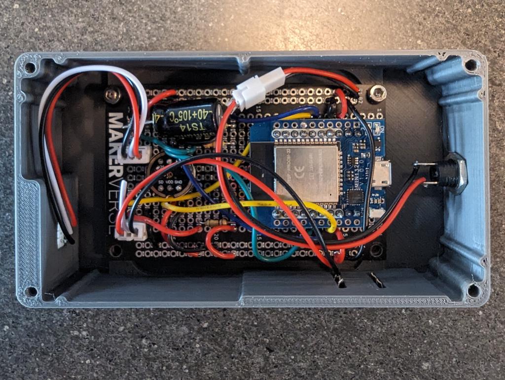
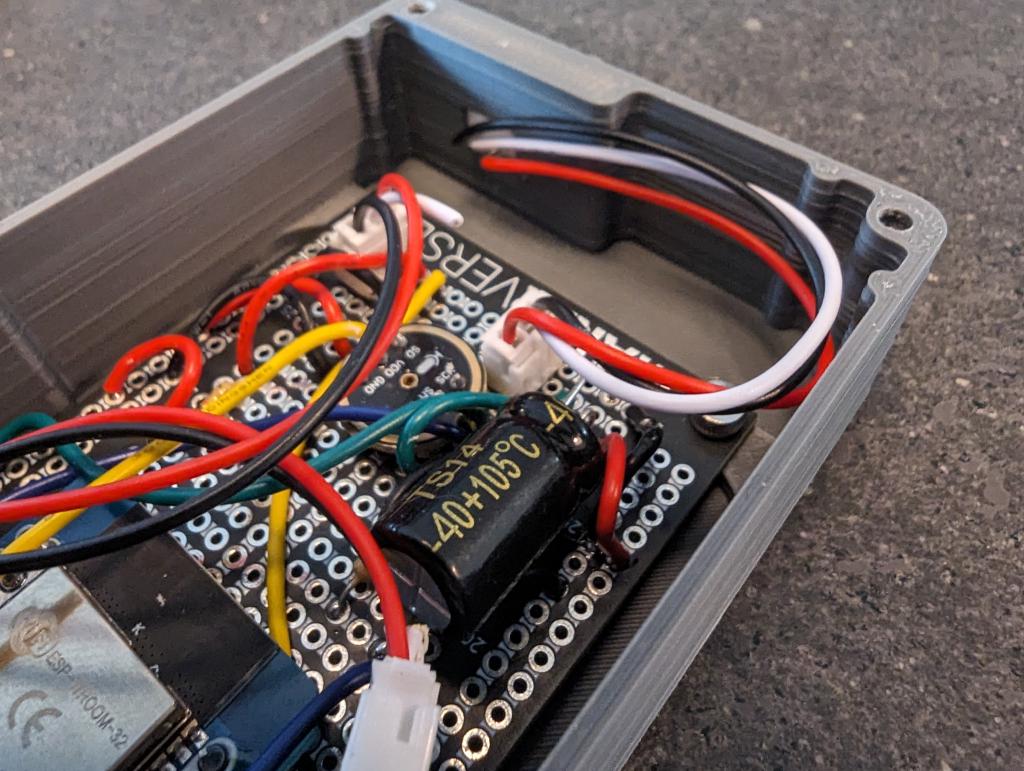
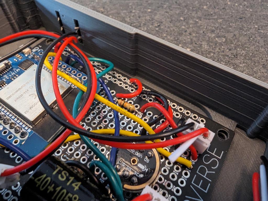
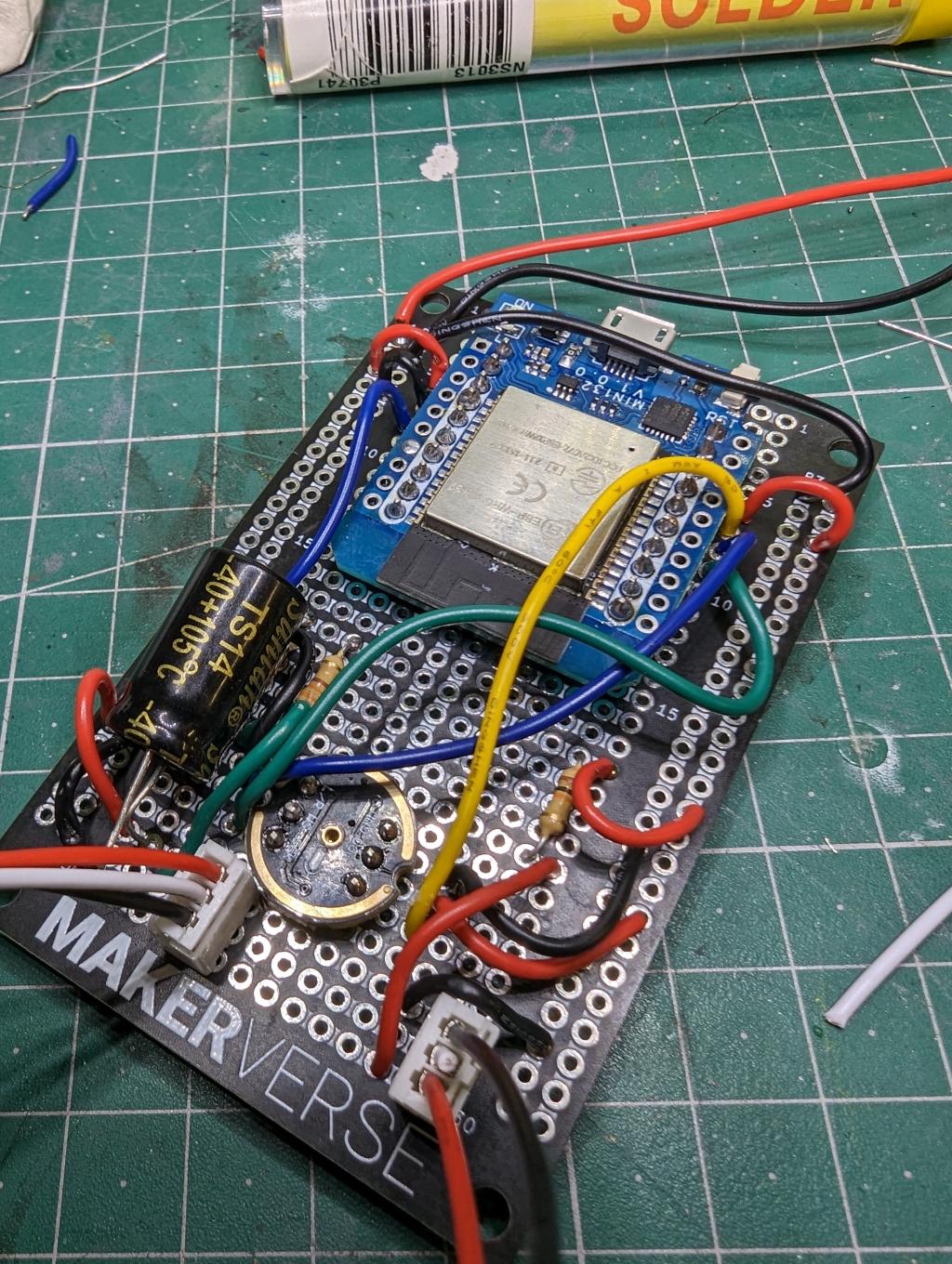 Take your time to solder the microcontroller and parts to the protoboard as per the schematic below. I used JST PH 2.0 breakout connectors so the board was independent of the actual power input, LED output and pushbutton. These were all connected to the case to make a neat package.
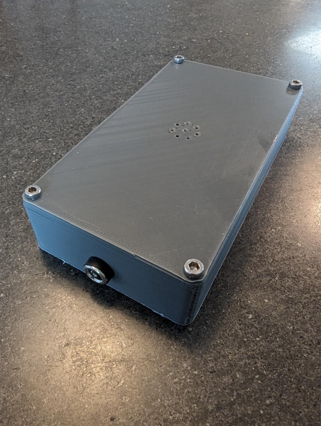
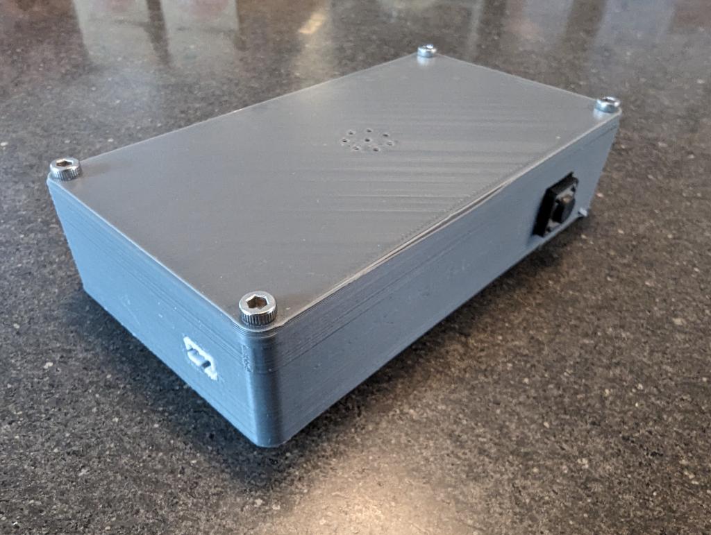
You can print the case if you want as well.
Firmware#
To get started, follow the Compiling WLED tutorial on their site. I used VSCode on a Macbook Pro, but YMMV. If you haven't already, best to flash an ESP32 with LED, setup a simple project and have a play with WLED and your LED strips. You want to be comfortable before embarking on this project.
To customise WLED for this project, include the file platformio_override.ini in the root directory (where platformio.ini already lives). The override file should contain:
[platformio]
default_envs = esp32dev

[env:esp32dev]
board = esp32dev
platform = ${esp32.platform}
platform_packages = ${esp32.platform_packages}
build_unflags = ${common.build_unflags}
build_flags = ${common.build_flags_esp32}
  -D WLED_RELEASE_NAME=ESP32
  -D WLED_DISABLE_BLYNK
  -D WLED_DISABLE_BLYNK
  -D WLED_DISABLE_CRONIXIE
  -D WLED_DISABLE_HUESYNC
  -D WLED_DISABLE_LOXONE
  -D USERMOD_AUDIOREACTIVE
  ${common.debug_flags}
  -D LEDPIN=16
  -D BTNPIN=17
  -D SR_DMTYPE=1 # defines digital microphone type
  -D I2S_SDPIN=5 # GPIO for SD pin on digital microphone
  -D I2S_WSPIN=23 # GPIO for WS pin on digital microphone
  -D I2S_CKPIN=19 # GPIO for SCK pin on digital microphone
  -D SR_SQUELCH=10 # Default "squelch" setting (10)
  -D SR_GAIN=10 # Default "gain" setting (60)
  #-D WLED_DISABLE_BROWNOUT_DET
lib_deps = ${esp32.lib_deps}
  https://github.com/blazoncek/arduinoFFT.git
monitor_filters = esp32_exception_decoder
board_build.partitions = ${esp32.default_partitions}
Assuming you used the same pins as my schematic, you shouldn't need to change anything. If you did, you might need to adjust some of the pin assignments above.
If you've done everything right and have connected the ESP32 to your machine via USB, you should be able to flash the device and then connect to it via wifi.
WLED Config#
Setting up segments#
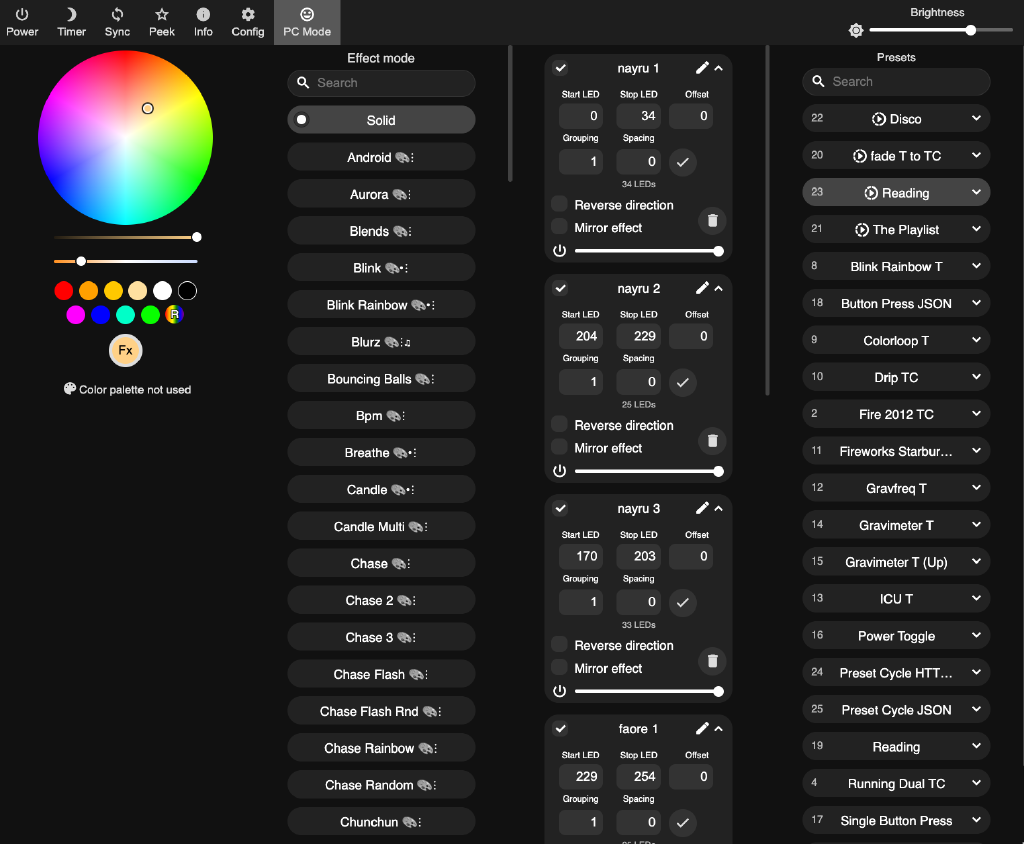
 So that you can address the triforce in the traditional 3 triangle layout, you need to setup the following segments in WLED
| Segment name | Start LED | End LED | Offset | Grouping | Spacing |
|---|---|---|---|---|---|
| nayru 1 | 0 | 34 | 0 | 1 | 0 |
| nayru 2 | 204 | 229 | 0 | 1 | 0 |
| nayru 3 | 170 | 203 | 0 | 1 | 0 |
| faore 1 | 229 | 254 | 0 | 1 | 0 |
| faore 2 | 103 | 136 | 0 | 1 | 0 |
| faore 3 | 137 | 169 | 0 | 1 | 0 |
| din 1 | 35 | 68 | 0 | 1 | 0 |
| din 2 | 69 | 102 | 0 | 1 | 0 |
| din 1 | 255 | 279 | 0 | 1 | 0 |
(Note - change the names as you see fit. We just used Zelda themed ones for fun. The important part is the start and end LEDs)
Creating functional playlists#
Create two playlists that will act as Macros and actually make the push button do something.
- Create one called Power Toggle and give it a specific ID (eg. 10). For this playlist, enter the API Command:
win&T=2 - Create one called Single button press and give it a specific ID (eg. 11). For this playlist, enter the API Command:
P1=20&P2=23&PL=~. This tells WLED that every time you press the button, it should cycle between Playlist 20-23. You can adjust this to those that fit your environment, but I have 4 playlists to fit different needs (Morning, Night, Music, Reading) and I set different Presets within each of those playlists.
Setting up button functions#
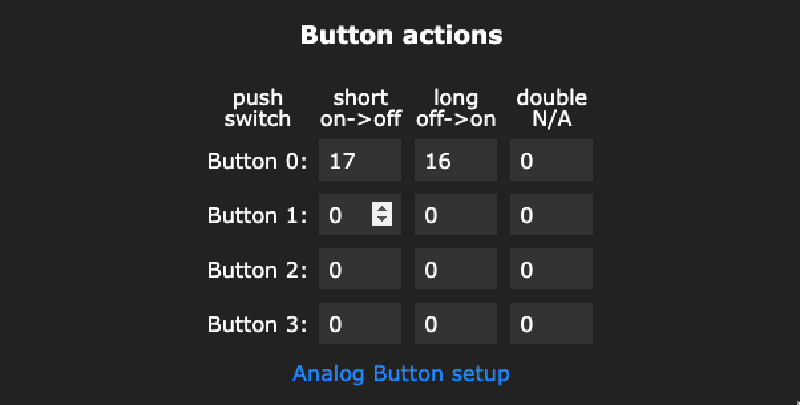
In the Time & Macros section, for the Buttons Actions for Button 0:
- Enter
11for 'Short on->off' (the Single button press playlist you created above) - Enter
10for 'Long off->on' (the Power Toggle playlist you created above)
Now when you save this, short pressing should cycle thru playlists. Long press should toggle power.
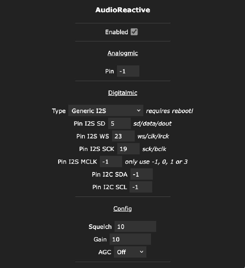
Configuring the microphone#
Most of the settings should be already set for the microphone, we did this in the firmware. But you might need to go to Settings / Usermods and choose Generic I2S as the Microphone type.
Home automation integration#
To control the light settings from OpenHAB (home automation), I do the following:
- First install the WLED Binding for OpenHAB
- OpenHAB should automatically discover your WLED "Thing". Add it in the usual way.
- Setup a few Items for the Thing, I've done these (substitute your channel name from the Thing in step 2 above):
Dimmer WLED_Dimmer  "LED [%s]"  <light>  (Lights_Kids) {channel="wled:json:wled:globalBrightness"}
String WLED_Presets "LED Presets"   {channel="wled:json:wled:presets"}
String WLED_Playlist "LED Playlist"   {channel="wled:json:wled:playlists"}
This allows you to do a few things with Rules now.
Switch the wall settings based on Hue change#
This rule watches a specific Hue lamp to become a specific colour. When it does, it changes the WLED Preset and 60 mins later turns it off. Essentially a nightlight.
rules.JSRule({
  name: "Enable LED wall when the nightlight is enabled",
  description: "",
  triggers: [
    triggers.ItemStateChangeTrigger("Hue_Kids_Lamp_Colour")
  ],
  tags: [],
  id: "Lighting_SyncLEDWall",
  execute: (event) => {
    // Specify the desired color you want to trigger the switch change
    var desiredColor = "260.951,100,4"; // Replace with your desired color values

    // Retrieve the current color of the Philips Hue lamp
    var lamp = items.getItem("Hue_Kids_Lamp_Colour");

    if(NightLightTimer !== undefined && NightLightTimer != null) {
      logger.info("Lamp timer was running. Cancelling it.");
      NightLightTimer.cancel();
    }

    // Check if the current color matches the desired color
    if (lamp.state == desiredColor) {
      logger.info("Lamp is in nightlight mode");
      // select the nightlight mode
      items.getItem("WLED_Dimmer").sendCommand(10);
      items.getItem("WLED_Presets").sendCommand("26");
      // let's set a timer to turn it off in 60 minutes
      NightLightTimer = actions.ScriptExecution.createTimer(
        time.ZonedDateTime.now().plusMinutes(60),
        () => {
          // turn off the light
          items.getItem("WLED_Dimmer").sendCommand(0);
        }
      );
    }
  }
});
Setting the current playlist#
Using the older Rules DSL language, you can also simply change the playlist currently running:
WLED_Playlist.sendCommand("11")Gallery#
Attachments & links#
- Triforce 3d printed connectors (zipped)
- Controller housing (zipped)
- Reddit discussion
- Makerverse 30 row Protoboard case on Printables
- Legend of Zelda Triforce LED Wall art on Printables
Github#
Coming soon